Table of Contents
Shear Force and Bending Moment
Shear Force – The shear force at any point along a loaded beam may be defined as the algebraic sum of all vertical forces acting on either side of the point on the beam.
The net effect of the shear force is to shear off the beam along with the point at which it is acting.
Shear force is taken +ve if it produces a clockwise moment and it is taken -ve when it produces an anticlockwise moment.
Bending Moment – Bending moment at any point along a loaded beam may be defined as the sum of the moments due to all vertical forces acting on either side of the point on the beam.
The bending moment tries to bend the beam. Clockwise moments due to loads acting to the left of the section are assumed to be +ve, while anticlockwise moments are taken -ve.
Sign Convention Used For Shear Force And Bending Moment
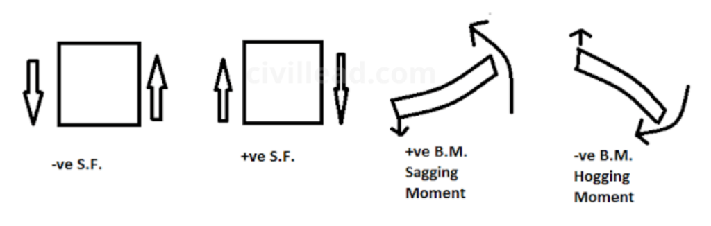
Shear Force – Force acting in the right-hand side of the section in the upward direction is taken -ve and force in the right-hand side of the section acting in the downward direction is taken as +ve.
Similarly, a force in the left-hand side of the section is taken +ve if it is acting in an upward direction and it is taken as negative if it is acting in a downward direction.
Bending Moment – First of all remove all the loads and reactions from any one side of the section. Now introduce each load and reaction one at a time and find its effect in the section.
A bending moment that causes concavity upwards is taken +ve and called a sagging bending moment. A bending moment that is causing convexity upwards is taken -ve and called a hogging bending moment.
Shear Force And Bending Moment Diagrams
A shear force diagram shows the shear force at every section of the beam due to transverse loading on it. Its baseline is equal to the span of the beam, drawn on a suitable scale.
For point loads S.F. diagram has a straight horizontal line, for UDL( Uniformly Distributed Load), It has straight inclined lines, and for uniformly varying loads it has a parabolic curve.
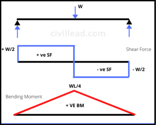
A bending moment diagram is a diagram which shows the bending moment at every section of the beam due to transverse loading on it.
In the case of a simply supported beam bending moment is zero at the ends, and for a cantilever, it is zero at the free end. For point loads, the B.M. diagram has straight inclined lines, for UDL, it has a parabolic curve and for the uniformly varying load, it has a cubic curve.
Important Points Must Be Kept In Mind While Drawing The Shear Force And Bending Moment Diagram
The following points must be kept in mind while drawing the shear force and bending moment diagrams.
1. First of all, consider either the left or the right-hand side of the section.
2. Add the forces( Including Reactions) normal to the beam on one of the side, if the right-hand side of the section is chosen, a force acting downwards is taken +ve while a force acting upwards is -ve.
3. The +ve values of shear force and bending moment are plotted above the baseline, and -ve values below the baseline.
4. The shear force diagram will decrease or increase suddenly shown by a vertical straight line at a section when there is a vertical point load.
5. The shear force between any two vertical loads will be constant and hence the shear force diagram between two vertical loads will be horizontal.
6. The bending moment at the two supports of a simply supported beam and also at the free end of a cantilever will be zero.
I hope now you have significant information about shear force and bending moment. Thanks for reading this article. Please, don’t forget to share it.
Also, Read
Difference Between Tension and Compression
Difference Between Pre Tensioning and Post Tensioning
Difference Between Beam and Column
What is Column?- Types of Column, Reinforcement and Design Procedure